| Home > All By Location regional map > Pittsbugh East > Panhandle Tunnel | |||
|
|
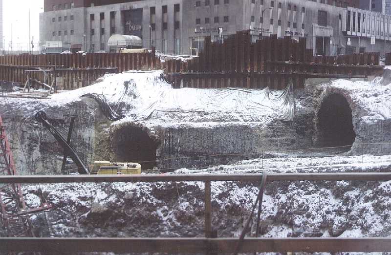
Photo by Bob Rathke, 2/11/68, PA canal tunnel (left) and Panhandle RR tunnel during construction of U.S. Steel Building [USX Tower] Panhandle Tunnel - Main information page Panhandle Tunnel - Detail photos Steel Plaza Subway Station Pittsburgh and Steubenville Extension Railroad Tunnel Between Fifth and Sixth Streets, East of Grant St Pittsburgh, Allegheny County, Pennsylvania HAER No. PA-70 Historic American Engineering Record Mid-Atlantic Region, National Park Service Department of the Interior Philadelphia, Pennsylvania 19106 Location: Between Fifth and Sixth Streets, east of Grant St, Pittsburgh, Allegheny County, Pennsylvania Date of Construction: 1863 Present Owner: Port Authority of Allegheny County Beaver and Island Avenues Pittsburgh, Pennsylvania 15233 Present Use: The railroad tunnel is being rehabilitated to serve as an underground right-of-way and station area (Midtown Station [Steel Plaza Station]) for the Light Rail Transit subway. Significance: The Pittsburgh and Steubenville Extension Railroad was a section of the Pittsburgh rail link between the Pennsylvania Railroad's western terminus and the eastern terminus of the Steubenville Railroad Company. When the rail link opened in 1865, it extended the Pennsylvania Railroad's trade and transportation network in Ohio, as far as Columbus. Project Information: The rehabilitation of the Pittsburgh and Steubenville Extension Railroad Tunnel to serve as a section of the Pittsburgh Light Rail Transit system is to be funded by the Urban Mass Transit Administration. Under Section 106 of the National Preservation Act of 1966, mitigative documentation was undertaken by the Port Authority of Allegheny County in 1982. Transmitted by: Jean P. Yearby, HAER, 1985, from information compiled by the Mid-Atlantic Regional Office, National Park Service Part 1. Historical Information A. Physical History 1. Date of erection: Construction for the tunnel began in December 1983 (sic). The precise date of completion is unknown; however, the entire Steubenville Extension was opened for train traffic on October 9, 1865, from Pittsburgh to Columbus. 2.* Architect: Unknown. 3. Original and subsequent owners: a) Pennsylvania Railroad Company: 1863 to 1968 b) Penn Central Transportation Corporation: 1968 to 1980 d) Port Authority of Allegheny County: 1980 to present 4.* Builder, contractor, suppliers: Unknown. 5. Original plans and construction: Original plans detailing tunnel construction are not available; however, one profile drawing, dating to October 28, 1901, has been located, which shows a double track tunnel of cut stone and brick construction with no invert (flat floor). The lower courses are cut stone, the upper courses consist of five rings of brick measuring a total of twenty-two inches thick. The walls beneath the spring line, the point where the curved arch meets the vertical wall, are shown to slope inward with a six to one batter, i.e., the inner face of the tunnel wall slopes inward one foot for every six vertical feet. The walls are shown to be supported by footers. In 1972, General Analytics, Inc. (GAI), a consulting engineering firm, prepared profile drawings of the railroad tunnel for the Port Authority's proposed Transit Expressway Revenue Line (the precursor of the Light Rail Transit Project) from information gathered by soil borings. These geotechnical drawings do not bear out the tunnel configuration shown in the 1901 map. GAI's drawings indicate that the exterior face of the cut stone tunnel wall does not parallel the interior face. Instead, the courses of cut stone gradually increase in thickness from the spring line to the base stone. Consequently, the exterior face slopes outward. Furthermore, the base stones rest directly upon bedrock; the walls are not supported by footers. Current Light Rail Transit excavation activities for the Midtown Subway Station confirm GAI's geotechnical drawings. In terms of construction, GAI's soil borings and LRT excavation activities indicate that the technique used was cut-and-cover. A trench, measuring approximately thirty-five feet wide, was excavaed from the ground surface, the tunnel was constructed within the trench, then the excavation was backfilled. At the time the soil borings were extracted, the bottom of the tunnel extended forty feet beneath the existing ground surface, which was an elevation of 780 feet above sea level. However, at the time of the tunnel's construction, the elevation of the ground surface was higher. In fact, the very need for a tunnel was created by a prominent feature of Pittsburgh's nineteenth century landscape known as Grant's Hill. The hill rose sharply from the confluence of the Allegheny and Monongahela rivers and posed serious problems for ground transportation westward. Thus, the tunnel penetrated the hill. Grant's Hill was leveled a total of approximately twenty feet on several occasions, subsequent to the tunnel's construction, in order to increase surface mobility. The excavation trench cut through thirty feet of bedrock to an elevation of approximately 740 feet above sea level, at which depth a floor was prepared for the tunnel. The sloping rocky sides of the trench were "corbeled" or stepped out to receive the cut stones that were to form the walls. Courses of cut stone were laid to the excavated rock line, which varied according to the slope of the trench. The average height of the side walls was eighteen feet. A five-course brick arch was then built upon the walls. 6. Alterations and additions: Some years after the tunnel was constructed, the southern end was lengthened during roadway construction. A 79.4 foot section of the tunnel, consisting entirely of cut stone, was appended to the south portal to carry Forbes Avenue over the railroad right-of-way. The height of this section measures 19.5 feet from the arch to the floor, two feet less than the height of the original tunnel. The tunnel was further widened around the turn of the century, in order to widen the overhead street and provide a sidewalk. A 19 +/- foot length was added to the newly-built southern portal. The clearance for this section measured 18.5 feet from roof to top of rail. Its wall consisted of ten courses of cut stone topped by a flat roof of girder construction. A decorative keystone arch and flanking retaining walls, both of cut stone, were constructed on the exterior. The latter form the existing south portal. A section of tunnel was exposed during the early twentieth century excavation activities for a garage complex. In several locations, the soil and bedrock were removed from the sides of the tunnel wall and a massive shell of concrete was poured to form footings. Steel girders were then placed on these footings to transfer the weight of the garage upon the concrete foundation. During the 1965-67 construction of the U. S. Steel Building, a section of the tunnel was removed including ther northern portal was removed. A new single track tunnel, measuring 409 feet long and 17.4 feet wide, was built within the subterranean levels of the building. The support systems for the tunnel and the building were designed to be independent of each other, so that train vibrations would not disturb thr building's structure integrity and the weight of the building would not bear down on the tunnel. The U. S. Steel Building tunnel begins 1,029.6 feet from the south portal, is rectilinear in design, and has two safety bays measuring one foot deep and approximately five feet wide. *Information pertaining to the construction of the tunnel is lacking; records documenting construction operations were housed at Union Station, the predecessor of the Pennsylvania Railroad station, formerly located at Liberty Avenue and Eleventh Street. Part II. Architectural Information A. General Statement: 1. Architectural character: Cut stone walls with a five-course brick arch, typical construction for Pittsburgh tunnels. 2. Condition of fabric: Many cut stones are disintegrating due to natural erosion processes. At numerous locations, elements of the brick ring have fallen off the tunnel arch. In a few sections, the entire inner brick ring was removed to prevent further fallings. The disintegration of bricks was possibly caused by water corrosion of the mortar between bricks and aided by the ibration induced by passing trains. Without the service of the inner ring, the structural strength has already been reduced to four-fifths of its original design value. B. Description of Exterior: 1. Overall Dimensions: At the spring line, the tunnel measures 24 feet from the inner faces of the stone wall. The tunnel is 21 feet high from arch to floor and 1,440 feet long from portal to portal. 2. Foundations: The walls supporting the arch and overlying backfill rest on rock without footings and displace the weight down through stones of increasing width. 3. Walls: The tunnel walls are built of cut stones measuring approximately 1.5 feet high, 1.5 to 2.5 feet long with a thickness varying from 2 to 3 feet. 4. Openings: A. Safety Bays: The 1980 LRT survey of the tunnel plotted the locations of five safety bays or escape niches, which allowed railroad employees to escape from the path of oncoming trains while working in the tunnel. The walls of the safety bays were usually formed by four courses of cut stone; the arch consisted of three courses of brick. a) Safety Bay #1 - located 207 +/- feet from the south portal on the right. Dimensions: 6 feet deep; 3 feet wide; 8 feet high. b) Safety Bay #2 - - located 378 +/- feet from the south portal on the left. Dimensions: 5.5 feet deep; 3.2 feet wide; 6 feet high. c) Safety Bay #3 - located 566 +/- feet from the south portal on the right. Dimensions: 7 feet deep; 3.5 feet wide; 6 feet high. d) Safety Bay #4 - located 736 +/- feet from the south portal on the left. Dimensions: 4 feet deep; 3.3 feet wide; 5.5 feet high. e) Safety Bay #5 - located 18 +/- feet from the south portal on the right. Dimensions: 6 feet deep; 3.5 feet wide; 6 feet high. f) Safety Bays #6 and #7 - located in the reconstructed section of the tunnel. Dimensions: 2 feet deep; 5 feet wide; 5.5 feet high. B. Portals: The present south portal is a cut stone arch consisting of sixteen cut stones and a central keystone. It is located beneath the south portion of Forbes Avenue near the Manor Building. The present north portal is the northern face of the U. S. Steel Building adjacent to Seventh Avenue. 5. Roof: The original section of the tunnel has a five-ring brick arch measuring twenty-two inches thick. C. Site: 1. General setting and orientation: Located in the central business district, the railroad tunnel cuts across the Pittsburgh Triangle in roughly a north-south direction. The tunnel is part of a line section known as the Pittsburgh-Steubenville Extension which includes a tunnel, a bridge and above-ground right-of-way. The line begins at the Pittsburgh Terminal (the Pennsylvania Railroad Station), runs above ground adjacent to the U. S. Post Office, goes underground for a 1/4 mile stretch at the U. S. Steel Building, emerges at the Manor Building, proceeds above ground to the north bank of the Monongahela River, then crosses the river on the Panhandle Bridge. The tunnel runs approximately forty feet beneath street level. 2. At the time of construction (1863), a steep hill, known as Grant's Hill, rose from the confluence of the Monongahela and Allegheny rivers. It impeded westward surface transportation to such a degree that the Pennsylvania canal and railroad systems opted to cut through the hill. Tunnels for both transportation systems are located in the same proximity. By the turn of the century, Grant's Hill had been leveled a total of approximately twenty feet to ease mobility. Part III. Sources of Information A. Bibliography: Burgess, George H. & Miles C. Kennedy. 1949. "Centennial History of the Pennsylvania Railroad Co. 1846-1946." PA RR Co. Philadelphia. Schotter, H. W. 1927. "Growth and Development of the Pennsylvania Railroad Co." 1846-1926. Submit info or inquiry - share some facts or ask a question. Introduction -- Nearby Structures Page created: Last modified: 27-Sep-2001 |
View Larger Map 
| |
| copyright: © Bruce S. Cridlebaugh 1999-2008 All Rights Reserved | |||